-
The study of antimagnetic rotation (AMR) has been a popular topic in weakly deformed or nearly spherical nuclei in the past few years. AMR is a novel mechanism for the generation of high angular momentum states in atomic nuclei and was first proposed by Frauendorf [1, 2]. In this interpretation, the two angular momentum vectors of a pair of deformation-aligned protons (
$ {\boldsymbol{j}}_{\pi} $ ) in reversed orbits are nearly perpendicular to the orientation of the total angular momentum vector of the valence neutrons ($ {\boldsymbol{j}}_{\nu} $ ) at the band head. An increase in the total angular momentum is generated by the simultaneous closing of the two proton blades along the direction of the total angular momentum vector, while the direction of the total angular momentum stays unchanged. It behaves like the closing of a pair of shears; hence, this type of excitation is known as the 'two-shears-like mechanism'. This geometry preserves the symmetry of$ R_{z}(\pi) $ [3] and causes the perpendicular components of the magnetic moments to precisely cancel each other out. In this scenario, the dipole transitions ($ M1 $ ) are not observed, and the energy levels in the bands are connected by weak$ E2 $ transitions, reflecting a nearly spherical core. Hence, the phenomenon of AMR is characterized by the appearance of weak$ E2 $ transitions, a decrease in the$ B(E2) $ values with increasing spin, and a large$ \Im^{(2)}/ B(E2) $ ratio [1].Experimentally, the observed AMR bands mainly focus on the
$ A\approx110,\;140 $ mass regions. Among them, firm experimental evidence of AMR arising from lifetime measurements has been reported in 105,106,107,108,109,110Cd [4−12], 100,101,103,104Pd [3, 13−18], and 142,143Eu [19, 20]. Moreover, several candidate AMR bands have been suggested in 111Cd [9], 102Pd [17], 108,109,110,112,113In [21−25], 102Ru [26], 144Dy [27], 127Xe [28], and 58Fe [29].Theoretically, AMR has been discussed using simple geometry in the classical particle-rotor model (PRM) [10, 11, 30], the cranking shell model with the particle-number-conserving method [31−34], and the tilted axis cranking (TAC) model [35]. For the TAC model, many applications have been performed in the framework of the microscopic-macroscopic model [5, 6, 13], pairing plus quadrupole model [2, 36], and covariant density functional theory (CDFT) [37−41]. In particular, using the point coupling effective interaction [42], TAC-CDFT not only successfully describes AMR, but also numerous other phenomena, such as magnetic rotation [43−46], chiral rotation [47−49], and the nuclear rod shape [50]. It is worth mentioning that for the famous chiral and magnetic rotation, the PRM has also achieved great success for the description of chiral doublet bands [51−54] and shear bands [55].
For most antimagnetic rotational nuclei, only one AMR band has been observed in a single nucleus. Is it possible for more than one antimagnetic rotational band to exist in a single nucleus, that is, multiple antimagnetic rotational bands? Such possibilities of multiple antimagnetic rotational band was recently demonstrated in 107Cd [8]. Therefore, it is interesting to explore more examples of multiple AMR and examine their two-shears-like manifestations in other nuclei. For this purpose, the neighboring isotone 105Pd and isotope 109Cd seem to be good candidates and are discussed here within the classical PRM.
-
To describe the interplay between the motion of particles and the collective rotation, Bohr and Mottelson [56] proposed to consider only a few valence particles, which move more or less independently in the deformed well of the core, and to couple them to a collective rotor that represents the remaining particles. This is the famous PRM, where one generally divides the Hamiltonian into two parts: a phenomenological part
$ H_{\rm coll} $ , which describes the inert core, and an intrinsic part$ H_{\rm intr} $ , which microscopically describes a valence particle or a whole subgroup of particles near the Fermi level [57]. As a quantum-mechanical model, the PRM has been successfully applied to investigate nuclear rotation [58−62]Recently, numerical calculations within the framework of a geometric model were devised to study the competition between the shears mechanism and core rotation [10, 11, 27, 30, 63]. In this model, high-j neutrons and high-j proton holes are represented by classical angular momentum vectors (blades). The total energy is expressed as the sum of the rotational energy of the core and an effective interaction of the form
$ V_{2}P_{2}(\theta) $ between the blades (see Eq. (1a)), which is similar to the Hamiltonian of the PRM, and the total energy is solved in the classical limit by the requirement that, at each spin, the shears angle minimizes the energy. Hence, the geometric model mentioned above is also known as the classical PRM by Macchiavelli and Clark [30, 63].The classical PRM, initially developed by Macchiavelli et al. for magnetic rotation [30, 64], was extended by Sugawara and Roy et al. for AMR bands [10, 11, 27]. During the last two decades, the characteristic properties of AMR bands have been reasonably described with the help of the classical PRM in many nuclei, such as 105,106,107,108,109,110,111Cd [8−11], 100,101,104Pd [3, 15, 16], and 127Xe [28]. In this study, we address the AMR character of the positive-parity band in 105Pd within the framework of the classical PRM. In this model, the energy
$ E(I) $ is given by$ \begin{aligned}[b] E(I)=&\frac{\mathit{\boldsymbol{R}}^{2}}{2\Im}+V_{2}P_{2}(\theta)\\=& \frac{({\boldsymbol{I}}-\mathit{\boldsymbol{j}}_{\pi}-{\boldsymbol{j}}_{\nu})^{2}}{2\Im}+\frac{V_{\pi\nu}}{2}\left(\frac{3{\rm cos}^{2}\theta-1}{2}\right)\\ &+\frac{V_{\pi\nu}}{2}\left(\frac{3{\rm cos}^{2}(-\theta)-1}{2}\right)- \frac{V_{\pi\pi}}{n}\left(\frac{3{\rm cos}^{2}2\theta-3}{2}\right). \end{aligned} $

(1) In Eq. (1b), the first term represents the rotational contribution, and the rest of the terms are the shear contributions. The second and third terms represent the repulsive interaction between the neutron particles and proton holes. The fourth term signifies the proton-proton (hole-hole) attractive interaction.
$ {\boldsymbol{j}}_{\pi} $ and$ {\boldsymbol{j}}_{\nu} $ represent the angular momentum vectors of protons and neutrons, respectively, and$ V_{\pi\nu} $ and$ V_{\pi\pi} $ are the interaction strengths. There is a scaling factor 'n' determined by the actual number of particle-hole pairs for a single-particle configuration. The angular momentum generated by the interplay between collective rotation and AMR can be calculated by minimizing the excitation energy as a function of shear angle, that is,$ {{\rm d}E(I)}/{{\rm d}\theta} $ =0$ \begin{equation} I=aj+2j{\rm cos}\theta+\frac{1.5\Im V_{\pi\nu}{\rm cos}\theta}{j}-\frac{6\Im V_{\pi\pi}{\rm cos}2\theta {\rm cos}\theta }{nj}, \end{equation} $

(2) or
$ \begin{equation} I=I_{\rm sh}+\Im \omega_{\rm sh}, \end{equation} $

(3) where
$ j = j_{\pi} $ ,$ a = {j_{\nu}}/{j_{\pi}} $ ,$ I_{\rm sh} $ is the sum of the first two terms of Eq. (2).$ \Im\omega_{\rm sh} $ represents the interplay between the shears mechanism and collective rotation and is represented by the last two terms of Eq. (2). The parameter$ \omega_{\rm sh} $ represents the frequency associated with the shears mechanism, which can be computed through$({{\rm d}E_{\rm sh}}/{{\rm d}\theta})/({{\rm d}I_{\rm sh}}/{{\rm d}\theta})$ , and is given by$ \begin{equation} \omega_{\rm sh}=\frac{1.5 V_{\pi\nu}{\rm cos}\theta}{j}-\frac{6 V_{\pi\pi}{\rm cos}2\theta {\rm cos}\theta }{nj}. \end{equation} $

(4) It must be noted that the magnitude of
$ \Im $ determines the extent of the interplay involved in generating the angular momentum in this model. The value of$ \Im $ can be estimated from the equation$ \begin{equation} \Im\omega|_{(\theta=0^{\circ})}=I_{\rm max}-I_{sh}^{\rm max}, \end{equation} $

(5) where
$ I_{\rm max} $ is the highest observed angular momentum state,$ I_{\rm sh}^{\rm max} $ is generated through AMR due to complete alignment of the proton holes ($ \theta=0^{\circ} $ ), and$ \omega_{\rm sh}|_{\theta=0^{\circ}}=\left(\frac{1.5V_{\pi\nu}}{j}\right)-\left(\frac{6 V_{\pi\pi}}{nj}\right). $

(6) In case of an AMR-plus-rotation model, the rotational frequency ω is given by
$ \begin{equation} \omega=\omega_{\rm rot}-\omega_{\rm sh}, \end{equation} $

(7) where
$ \omega_{\rm rot}=\dfrac{1}{2\Im_{\rm rot}}(2I+1) $ is the core rotational frequency, and$ \Im_{\rm rot} $ is the core moment of inertia, whose value can be estimated from the slope of the$ I(\omega) $ plot of the ground-state band (before neutron alignment). The details of this classical model are given in Refs. [10, 11]. Thus, all the parameters of the present model can be fixed either from experimental data or the systematics of the mass region. -
In a previous study, multiple AMR was proposed for the first time in a pair of signature partner bands 5 and 6 of 107Cd with the configuration
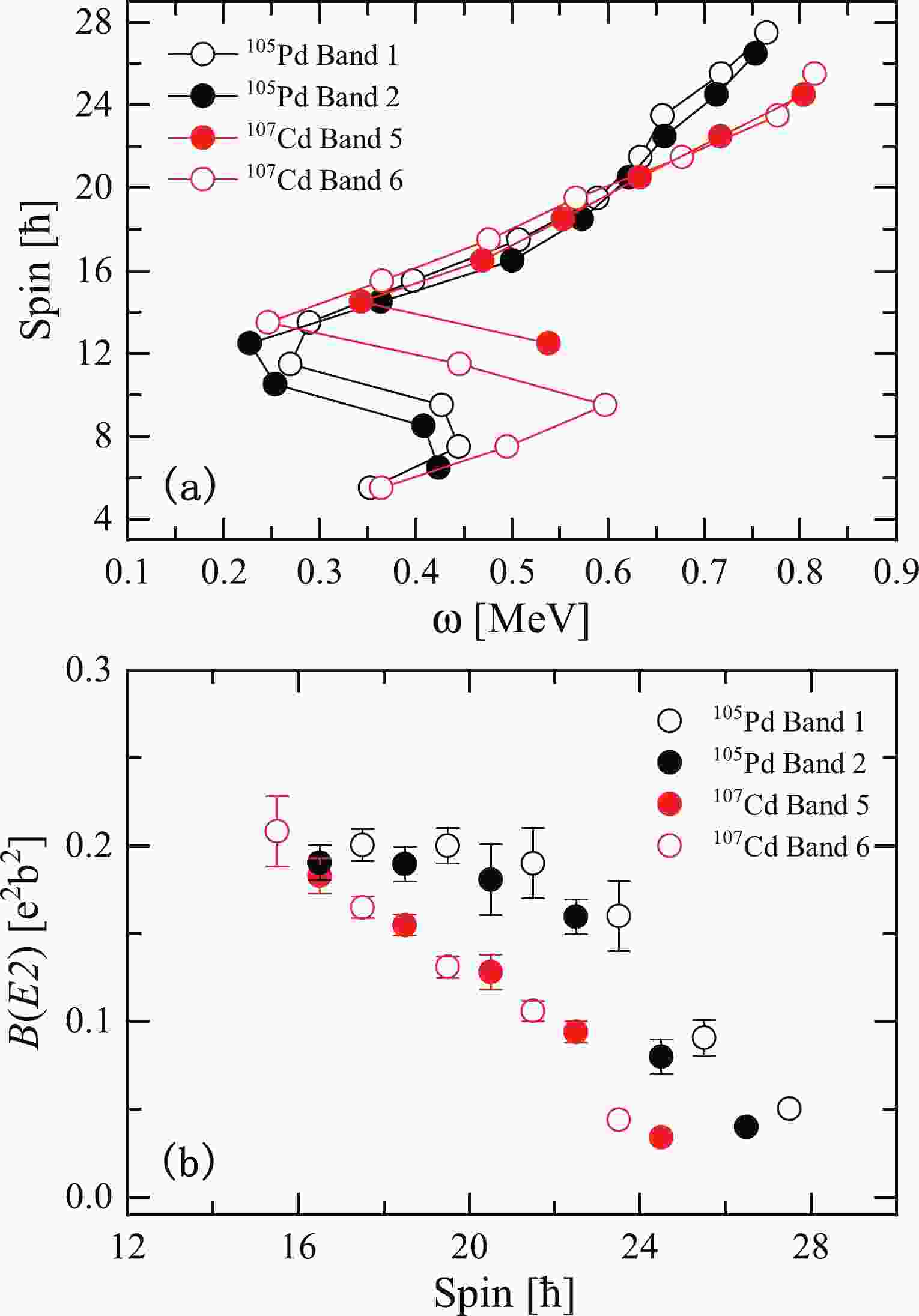
$ \pi(g_{9/2}^{-2})\otimes \nu(g_{7/2}h_{11/2}^{2}) $ [8]. In the present study, we find that similar structures labeled bands 1 and 2 are also observed in the neighboring isotone 105Pd. To further study the characteristics of the bands in 105Pd, a$ I(\omega) $ plot of bands 1 and 2 in 105Pd is shown in Fig. 1(a) and compared with bands 5 and 6 in 107Cd [8], which are interpreted as a pair of antimagnetic rotational bands. In Fig. 1(a), bands 1 and 2 of 105Pd exhibit sharp backbends with an increase in aligned angular momentum of approximately 8$ \hbar $ at frequency$ \hbar\omega \sim $ 0.4 MeV. The backbends are due to the alignment of two neutrons in the$ h_{11/2} $ orbital, which is the lowest band crossing in this mass region. Furthermore, note that bands 1 and 2 of 105Pd and bands 5 and 6 of 107Cd exhibit similar behavior, including the frequencies of the observed alignments and the corresponding increases in spin, which indicates that the bands of 105Pd are likely built on the similar intrinsic configuration$ \pi(g_{9/2}^{-4})\otimes \nu(g_{7/2}h_{11/2}^{2}) $ .
Figure 1. (color online) Comparison of the spin angular momentum (a) and
$B(E2)$ values (b) for bands 1 and 2 of$^{105}$ Pd and bands 5 and 6 of$^{107}$ Cd [8].In Fig. 1(b), the
$ B(E2) $ values of bands 1 and 2 in 105Pd taken from Ref. [65] are compared with the corresponding data for bands 5 and 6 in 107Cd. It is easy to see that the$ B(E2) $ values exhibit similar behaviors in bands 1 and 2 of 105Pd as well as bands 5 and 6 of 107Cd, which show decreasing$ B(E2) $ values with increasing spin. These properties agree well with the experimental characteristics of AMR. Indeed, bands 5 and 6 in 107Cd have been suggested to be antimagnetic rotational bands. Hence, both bands 1 and 2 of 105Pd may have a common origin from AMR.To further investigate the corresponding rotation mechanism of the positive-parity bands 1 and 2 in 105Pd, the classical PRM is performed. In calculations, the corresponding single particle configuration for bands 1 and 2 of 105Pd is
$ \pi(g_{9/2}^{-4})\otimes\nu(g_{7/2}h_{11/2}^{2}) $ . This configuration has twelve proton-neutron combinations (n=12), and the interaction strengths$ V_{\pi\nu} $ and$ V_{\pi\pi} $ for both bands are expected to be 1.2 and 0.15 MeV, respectively, based on the systematic study of AMR bands in the A$ \approx 110 $ mass region [3, 11, 16].In Fig. 2(a), the experimental angular momentum as functions of frequency for bands 1 and 2 are compared with the classical PRM calculations for the proposed configuration. As shown in Fig. 2(a), the calculations are in general agreement with the trend of the experimental angular momentum of bands 1 and 2, supporting the configuration assignment of the bands.

Figure 2. (color online) Comparison of the measured I vs ω (a) and
$B(E2)$ vs I (b) for bands 1 and 2 of$^{105}$ Pd. The red line represents the values calculated using the classical particle-rotor model. Values of$j_{\pi}$ = 6$\hbar$ ,$\Im$ = 13.91$\hbar^{2}$ MeV$^{-1}$ , and$\Im_{\rm rot}$ = 18$\hbar^{2}$ MeV$^{-1}$ have been used for both bands 1 and 2. The$j_{\nu}$ values of band 1 and 2 are 13.5$\hbar$ and 12.5$\hbar$ , respectively.Typical characteristics of AMR include weak
$ E2 $ transitions, reflecting the small deformation of the core, and a decreasing tendency of the reduced transition probability$ B(E2) $ values with increasing spin, which results in large ratios of the dynamic moments of inertia$ \Im^{(2)} $ to the$ B(E2) $ values. Within the classical model description of the twin-shears mechanism for AMR, the$ B(E2) $ values can be written as$ \begin{equation} B(E2)=\frac{15}{32\pi}(eQ_{\rm eff})^{2}{\rm sin}^{4}\theta. \end{equation} $

(8) The
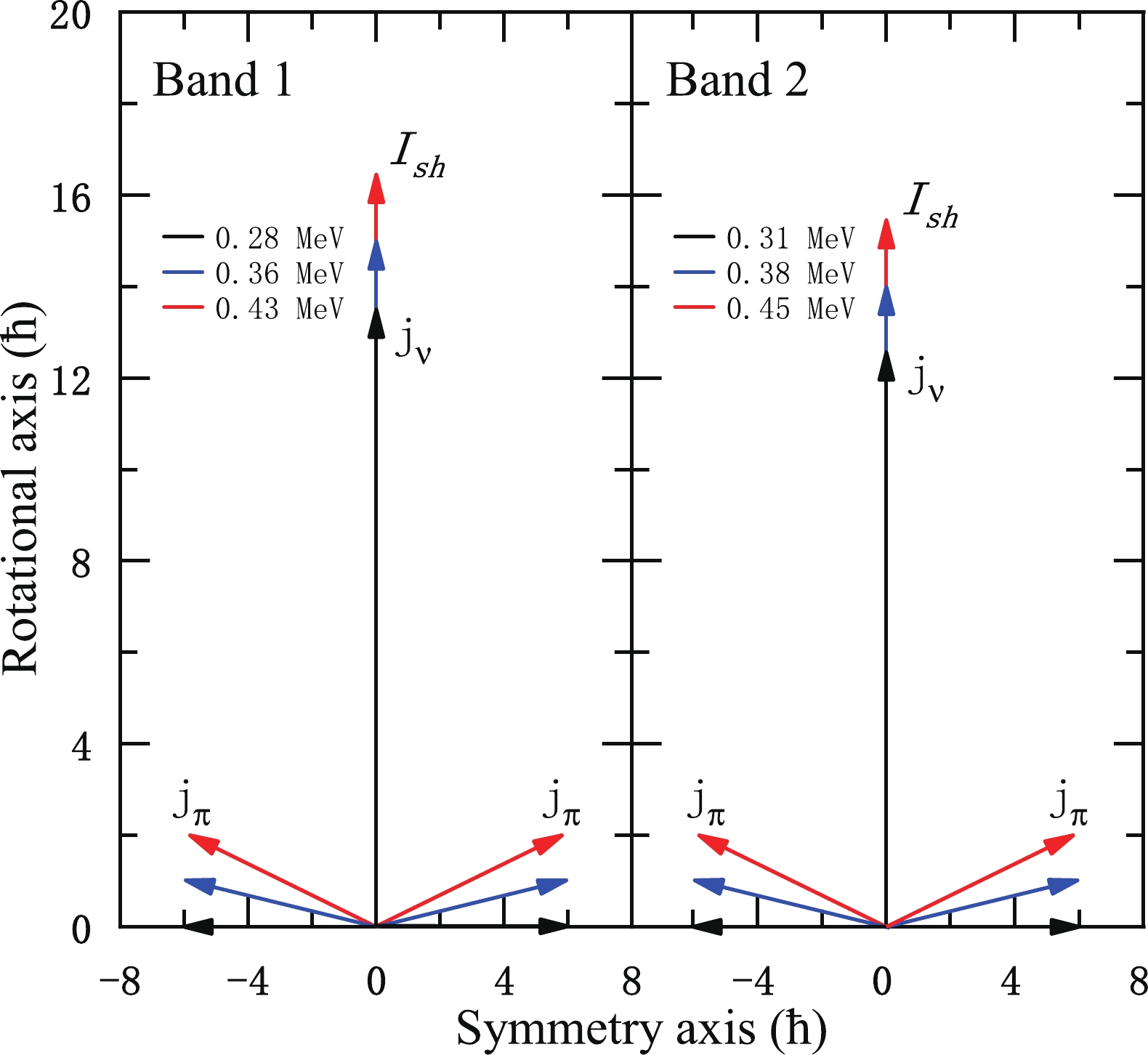
$ B(E2) $ values have been calculated using Eq. (8) for$ eQ_{\rm eff} $ = 1.3 eb [16], where θ and the total angular momentum are related by Eq. (2). The calculated$ B(E2) $ values are shown by the red lines in Fig. 2(b). It is interesting to note that the calculated$ B(E2) $ values of both bands 1 and 2 in 105Pd exhibit a monotonically decreasing behaviour with increasing angular momentum, which agrees well with the experimentally obtained values taken from Ref. [65]. Moreover, the values of$ \Im^{(2)}/B(E2) $ are also calculated, and it is found that the values are substantial ($ > $ 100$ \hbar^{2} $ MeV-1(eb)-2). These results are consistent with the characteristics of AMR.It is worth noting that the shears angle (θ) is the only variable in the present model, and every angular momentum state corresponds to a unique θ, which is determined from Eq. (2). To examine the two-shears-like mechanism for the candidate AMR bands in 105Pd, a pictorial representation of the generation of the angular momentum by the closing of the twin-shears structure over the observed spin range in 105Pd is shown in Fig. 3. For the signature partner bands 1 and 2 of 105Pd with the
$ \pi(g_{9/2}^{-4})\otimes \nu(g_{7/2}h_{11/2}^{2}) $ configuration, the angular momentum vectors$ {\boldsymbol{j}}_{\pi} $ are almost perpendicular to$ {\boldsymbol{j}}_{\nu} $ at the bandhead. Together with the valence particle angular momentum vectors$ {\boldsymbol{j}}_{\nu} $ , they form the blades of the two shears. With increasing rotational frequency, the gradual alignment of the proton hole angular momentum vectors toward the particle vectors generates a higher angular momentum. Because the direction of$ {\boldsymbol{I}}_{\rm sh} $ remains unchanged, the two shears simultaneously close by moving one blade toward the other. In such a way, the two-shears-like mechanism in 105Pd is clearly demonstrated in Fig. 3.
Figure 3. (color online) Angular momentum vectors of the two-shears-like orbits,
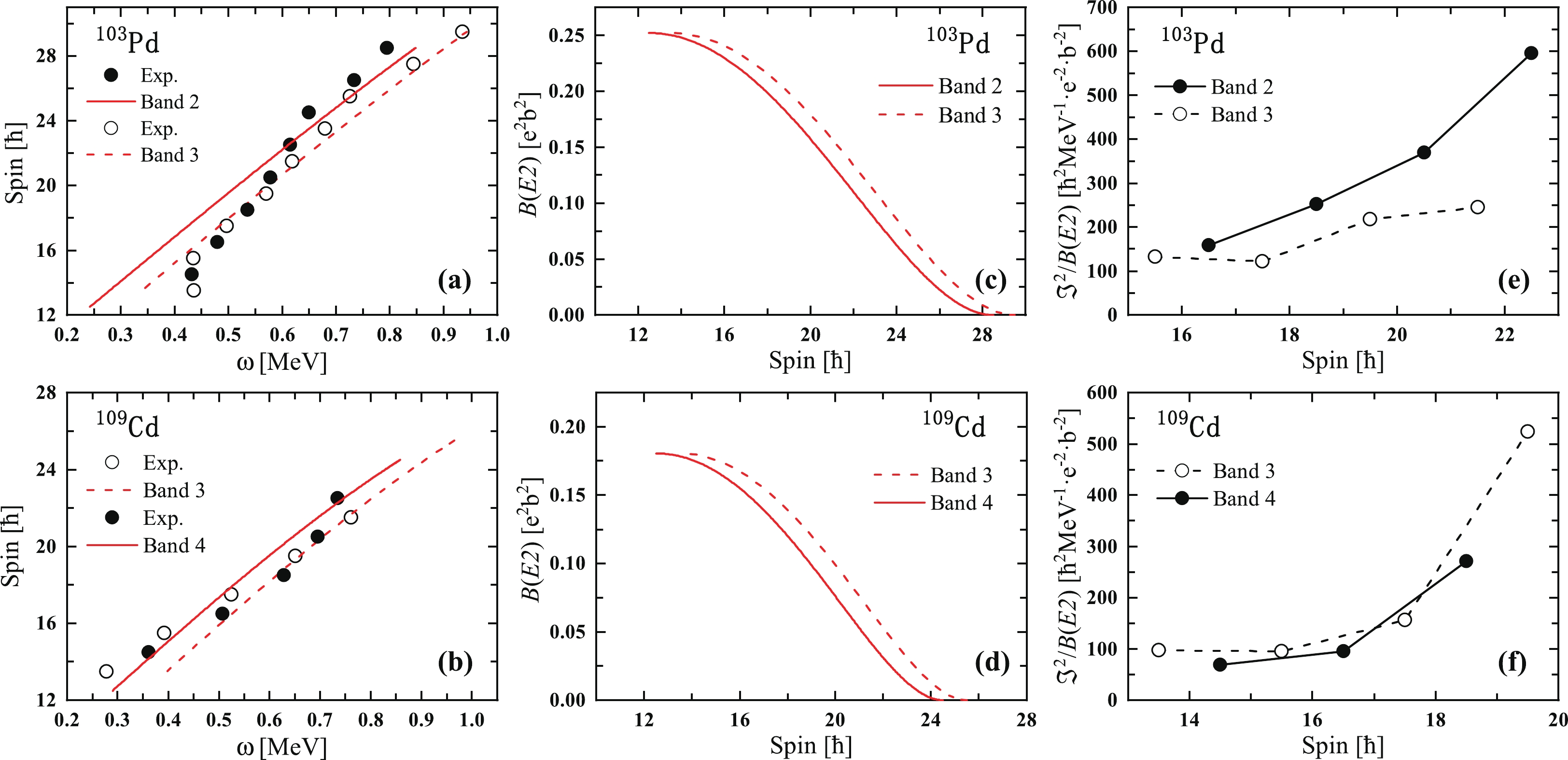
${\boldsymbol{I}}_{\rm sh}$ , contributed from four proton holes$g_{9/2}^{-4}$ and neutron particles$g_{7/2}h_{11/2}^{2}$ for candidate AMR bands in$^{105}$ Pd calculated with the classical model.Furthermore, positive-parity signature partner bands with the same neutron configuration have also been found in neighboring 103Pd and 109Cd nuclei [66, 67]. As shown in Figs. 4(a) and (b), the
$ I(\omega) $ plot for the positive-parity signature partner bands of 103Pd and 109Cd is calculated using the classical PRM and compared with the experimental angular momentum. The calculated values are plotted as red lines in Figs. 4(a) and (b) for$ V_{\pi\nu} $ = 1.2 MeV and$ V_{\pi\pi} $ = 0.15 MeV. It is evident from the figures that the calculations are in general agreement with the trend of experimental angular momentum for the signature partner bands, which further supports the previous configuration assignment.
Figure 4. (color online) Observed
$ I(\omega) $ plots [(a), (b)], plot of spin vs$ B(E2) $ [(c), (d)], and plot of spin vs$ \Im^{(2)}/B(E2) $ [(e), (f)] for 103Pd and 109Cd. The red line in (a), (b), (c), and (d) represents numerical values obtained from the classical particle-rotor model. For band 2 in 103Pd,$ j_{\pi} $ = 6$ \hbar $ and$ j_{\nu} $ = 12.5$ \hbar $ , and for band 3,$ j_{\nu} $ = 13.5$ \hbar $ . For 109Cd,$ j_{\pi} $ = 4.5$ \hbar $ and$ j_{\nu} $ = 13.5$ \hbar $ in band 3, and$ j_{\nu} $ = 12.5$ \hbar $ in band 4. The value of$ \Im $ = 13.91$ \hbar^{2} $ MeV-1 is used for 103Pd, and for 109Cd,$ \Im $ = 11.26$ \hbar^{2} $ MeV-1. The$ \Im_{\rm rot} $ value is 18$ \hbar^{2} $ MeV-1 for 103Pd and 13$ \hbar^{2} $ MeV-1 for 109Cd.The calculated
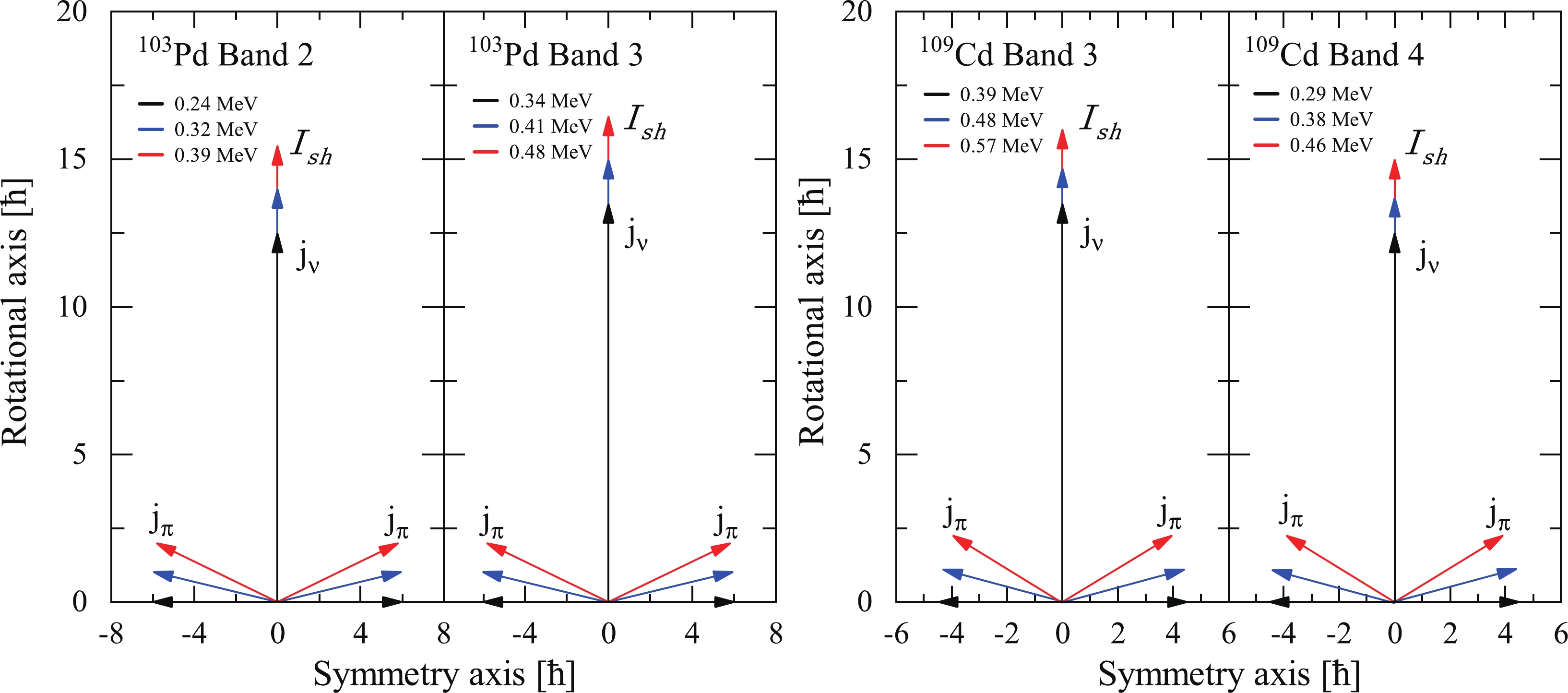
$ B(E2) $ values and$ \Im^{(2)} $ /$ B(E2) $ ratios are also shown as functions of the rotational frequency in the present calculations for the assigned configurations in Fig. 4. The value of$ eQ_{\rm eff} $ is taken as 1.3 eb for 103Pd [16] and 1.1 eb for 109Cd [11]. As shown in Figs. 4(c) and (d), the$ B(E2) $ values exhibit smooth decreasing tendencies with increasing rotational frequency in the calculations for all bands. However, in Figs. 4(e) and (f), the calculated$ \Im^{(2)} $ /$ B(E2) $ ratios ($ > $ 100$ \hbar^{2} $ MeV-1(eb)-2) are significantly higher than the values for the well deformed band [9]. As mentioned above, the features of the positive-parity band in 103Pd and 109Cd are generally consistent with the fingerprints of AMR. Indeed, similar to 105Pd, the two-shears-like mechanism in 103Pd and 109Cd is clearly demonstrated in Fig. 5. -
In this paper, the candidate multiple antimagnetic rotational bands in 103,105Pd and 109Cd are discussed using the classical PRM. For 105Pd, the configuration of the signature partner bands is assigned to
$ \pi(g_{9/2}^{-4})\otimes\nu(g_{7/2}h_{11/2}^{2}) $ , and the calculated results of the$ I(\omega) $ plot further support this assignment. The calculated$ B(E2) $ values show good agreement with the experimentally determined$ B(E2) $ values, supporting the AMR characteristics of the signature partner bands in 105Pd. Furthermore, the present calculations for the 103Pd and 109Cd nuclei predict a negative slope for the$ B(E2) $ values with increasing spin and a large$ \Im^{(2)}/B(E2) $ ratio ($ > $ 100$ \hbar^{2} $ MeV-1(eb)-2). These characteristics are consistent with the fingerprints of AMR, which suggests that the signature partner bands in 103Pd and 109Cd may also be candidates for AMR bands. However, to further confirm this suggestion, experimental results of the absolute$ B(E2) $ transition probabilities based on lifetime measurements are desirable.
Possible multiple antimagnetic rotational bands in odd-A 103,105Pd and 109Cd nuclei
- Received Date: 2022-03-03
- Available Online: 2022-09-15
Abstract: The positive-parity signature partner bands in 103,105Pd and 109Cd nuclei are investigated using the classical particle-rotor model. Based on the systematic study of neighbouring nuclei, the signature partner bands of 105Pd are assigned to the


 Abstract
 HTML
HTML Reference
 Related
 PDF
PDF


 DownLoad: